|
Click here for complete Site Map
Please note - the text and images on this page were very kindly donated by Steven Weston to help other Optima owners service their cameras. I (Roland) have not yet worked on an Optima camera - but hopefully will extend and enhance the pages here as I discover more Optima repair info.
Cleaning the Viewfinder
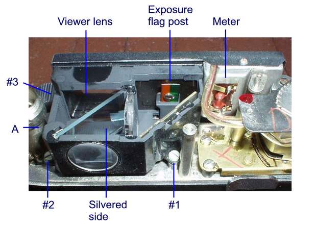
This photo shows the Viewfinder Assembly with its Top Cover already removed (I put the assembly back in the camera for this photo). Do not remove the Top Cover, yet.
The photo shows the Meter electronics in the top right. The Exposure Flag Post, top centre, projects into the Viewfinder Assembly through a hole in the bottom of the assembly. The Viewer Lens, top left, is cemented into the frame of the assembly, but the cement may have failed, leaving the lens loose.
The triangular area between the Exposure Flag Post and Screw #1 is bounded by the Bright Line Mask at the front, a focusing lens on the left, and a front-surfaced mirror on the back-right. Do not attempt to clean the front-surfaced mirror. There is little to be gained visually, and much at risk, by cleaning these components. Just dust them off.
Also note the silvered side of the beamsplitter Do not attempt to clean the silvered side because you may loose your bright line display. With those caveats let's begin.
- Remove screws #1, #2, and #3. Lift the Viewfinder Assembly upward taking care to let the Exposure Flag Post slip through its opening in the bottom of the assembly.
- Remove screw A. Remove the Top Cover of the assembly.
-
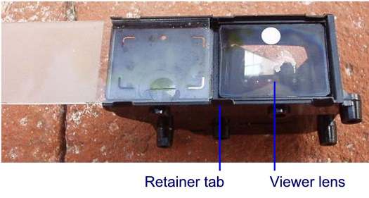
This photo shows the front of the Viewfinder Cover Glass has been slid to the left to expose the Viewer Lens. Note that the six Retainer Tabs are nothing more substantial than plastic that has been melted and formed to hold the Cover Glass. Carefully slide the Cover Glass to the left and remove it from the assembly. Set it aside for now.
- Using a cotton applicator, gently push the front and back sides of the Viewer Lens to determine if it is still firmly cemented into place. If it moves at all, gently push it towards the front and remove it from the assembly.
- Cleaning Caveats: Do not use solvents on the edges of the Viewer Lens or the Viewfinder Assembly. The paint used inside of the assembly appears to be water soluble. The black paint on the Viewer Lens edges reduce lens flare. The silver dot on the front of the Viewer Lens can be removed by some solvents. The silvered side of the Beam Splitter can be removed by some solvents.
- If necessary, clean or remove any loose glue from the Viewer Lens and the Viewfinder Assembly. Blow out any dust from the inside of the Viewfinder Assembly. Using ethyl alcohol, and taking care of the Beam Splitter's silvered side, clean the inside surface of the Eyepiece Lens. Now clean the non-silvered side of the Beam Splitter and the back side of the Viewer Lens.
- If necessary, reattach the Viewer Lens to the assembly by using a toothpick to apply a small amount of Pliobond to the top and bottom inside edges of the assembly that will be in contact with the Viewer Lens. While the Pliobond is tacky, push the Viewer Lens into place. While the Pliobond sets, put the assembly aside and proceed to the next step.
- Use ethyl alcohol to clean the front and back side of the Cover Glass. The Cover Glass is very thin and easily broken. If there are finger oil marks on the ground glass, use acetone and a cotton applicator to remove them -- they will evaporate away.
- Clean the front side of the Viewer Lens (after the Pliobond has set).
- Carefully slide the Cover Glass into the Viewfinder Assembly. Use a bit of Pliobond at the corners of the left-front of the assembly to fix the Cover Glass in place.
- After all glue has dried, and a final dust blow-out, replace the Top Cover of the assembly by first fitting it to the edge that has screw A and gently snapping it into position. Reattach screw A. Take look through the Viewfinder. How much clearer is it?
- Carefully lower the Viewfinder Assembly onto the camera taking care to let the Exposure Flag Post slip through its opening in the bottom of the assembly. Reattach screws #1, #2, and #3.
- Use ethyl alcohol to clean the back side of the Eyepiece Lens. Take look through the Viewfinder. Check the operation of the Exposure Flag. If all looks good, you can proceed to reassemble the Top Plate.
Top Plate Reassembly
- Carefully lower the Top Plate onto the camera. Before it will lower all of the way on the Rewind side of the camera, you must first use a dental pick to pull the Rewind Release Lever to the back of the camera so that the lever's Release Tab clears the top of the Rewind Shaft. Once fully lowered, the Release Tab should be seen projecting through the slot in the Rewind Shaft.
- Use a spanner to reattach the Rewind Retainer Ring. Don't over-tighten!
- Reattach the Black Screw that was beneath the Spring Clip.
- Reattach the Right Plate Screw.
-
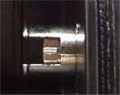
Insert the Rewind Key Shaft into the Rewind Fork Shaft from below. Use an angled dental pick to position the Key Shaft's key into the slot of the Rewind Fork Shaft (see photo). Use the dental pick to push it upwards and keep it there. From above, drop the Rewind Spring into the opening of the Rewind Shaft. The top end of the Rewind Spring is more tightly coiled. Screw the Rewind Knob onto the Rewind Key Shaft. To fully tighten, use a screwdriver blade or other tool inserted in the Rewind Shaft Fork and turn the Rewind Knob clockwise.
- Reattach the Accessory Shoe Spring Clip by sliding it into the bottom of the shoe. Screw in the Accessory Shoe Stop.
- Reattach the Film Speed Knob being careful to engage its notch on the bottom with the pin of the setting plate below. They should engage at 100/21. Use a spanner or divider to reinstall the centre bezel of the Film Speed Knob. Do the same for the Film Speed Catch.
- Use a spanner or dividers to reattach the Rewind Release. There should not be any leftover parts.
- Clean the camera's surfaces, load some film and make some great pictures.
Got a question or can't find the info you are looking for? Click HERE to contact us.
Click here for main Repair Page
Click here for complete Site Map
|